
Request form for CANopen Bit Timings
Please fill out the following two fields to specify the used CAN clock rate and desired sampling point location and then press submit. The sample point for CANopen bit timings is at 87.5%.
Recommended bit timing settings according to CiA-301 V4.2
Bit Rate | Nominal bit time tb | Valid range for location of sample point | Recommended location of sample point |
1 Mbit/s | 1 µs | 75% to 90% | 87,5% |
800 kbit/s | 1,25µs | 75% to 90% | 87,5% |
500 kbit/s | 2µs | 85% to 90% | 87,5% |
250 kbit/s | 2µs | 85% to 90% | 87,5% |
125 kbit/s | 2µs | 85% to 90% | 87,5% |
50 kbit/s | 2µs | 85% to 90% | 87,5% |
20 kbit/s | 2µs | 85% to 90% | 87,5% |
10 kbit/s | 2µs | 85% to 90% | 87,5% |
You can use the table in Philips SJA1000 mode (Like Philips or Intel) for controllers like:
- Philips 82C200, SJA1000
- Intel 82527
- Infineon (Siemens) C167CR, C515C, XC161C, XC164C, TwinCAN SAK82C900
- SPANSION (reported from Ralf Ebeling) and acknowledged by us for MB9054x
- Dallas 80c390 Dual CAN
- Toshiba TCAN
- Freescale msCAN (HCS12)
- Renesas RL78F (RSCAN)
or select:
- the Freescale TouCAN/FlexCAN module,
- the Texas Instruments TMS320 (TMS320F2407, TMS320F28xx),
- the ATMEL CANary
- the ATMEL AT91SAM9263 (for AT91SAM7A3 and AT91SAM7X, too),
- the BOSCH C_CAN (C8051xxx, MB96xxx, STR7xx, STR9xx...),
- the Microchip CAN/ECAN (PIC18F, dsPic30, dsPic33),
- the Renesas M16C/29,
- the Renesas M32C/87 CAN,
- the Renesas RCAN (H8SX).
- the Renesas RSCAN

The question arises:
what exactly is the sample point?
The picture shows you the time segments of a
CAN-Bit as defined by ISO-11898.
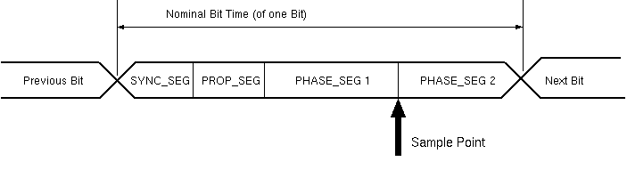
| Sync_Seg: | 1 tq |
| Prop_Seg + Phase_Seg1: | 1 .. 16 tq |
| Phase_Seg2: | 1 .. 8 tq |
| (Table calculation uses Prop_Seg = 0) | |
A detailed description about setting
the correct CAN bit timing is given
in a paper by Florian Hartwich and Armin Bassemir
by Robert Bosch:
The Configuration of the CAN Bit Timing.
Basically the CAN bit period can be subdivided
into four time segments.
Each time segment consists of a number of
Time Quanta - tq- smallest time unit.
- SYNC_SEG is 1 Time Quantum long.
It is used to synchronize the various bus nodes. - PROP_SEG is programmable to
be 1, 2,... 8 Time Quanta long.
It is used to compensate for signal delays across the network. - PHASE_SEG1 is programmable to
be 1,2, ... 8 Time Quanta long.
It is used to compensate for edge phase errors and may be lengthened during resynchronization. - PHASE_SEG2 is the maximum of PHASE_SEG1
and the Information Processing Time long.
It is also used to compensate edge phase errors and may be shortened during resynchronization. For this the minimum value of PHASE_SEG2 is the value of SJW. - Information Processing Time is less than or equal to 2 Time Quanta long.
- The total number of Time Quanta has to be from 8 to 25.
Programming of the Sample Point allows optimizing the Bit Timing: A late sampling for example allows a maximum bus length: an early sampling allows slower rising and falling edges.
TouCAN
The TouCAN module uses three 8-bit registers to set-up
the bit timing parameters required by the CAN protocol.
Control registers 1 and 2 (CANCTRL1, CANCTRL2)
contain the
PROPSEG = PROP_SEG( Bit 0-3 in CANCTRL1),
PSEG1 = PHASE_SEG1 (Bit 3-5),
PSEG2 = PHASE_SEG2 (Bit 0-2),
und the RJW (Bit 6-7 in CANCTRL2) fields
which allow the user to configure the bit timing parameters.
The prescaler divide register (PRESDIV) allows the user
to select the ratio used to derive the clock from
the system clock.
For the position of the sample point only the relation
(SYNC_SEG + PROP_SEG + PHASE_SEG1) / (PHASE_SEG2) is important.
The absolute value of PROPSEG = PROP_SEG is
rather of academic interest and is not calculated by the program.
The values for PRESDIV, PROPSEG, PSEG1 and PSEG2 are calculated.
SJA1000
The SJA1000 uses only two 8-bit registers to set-up
the bit timing parameters required by the CAN protocol.
One register BTR0 containing the value
of the bit timing prescaler and the other for the values
of PHASE_SEG1 and PHASE_SEG2.
PHASE_SEG1 is used for programming both (PROP_SEG + PHASE_SEG1)
according CAN specification.
For 125 kbit/s and 16 tq at 16 (8)Mhz - sja100
BTR0 = 3, BTR1 = 1C.
For 125 kbit/s and 16 tq at 20 (10)Mhz - C515C
BTR0 = 4, BTR1 = 1C
CANary
The CANary module used by ATMEL for the T89C51 and CAN-AVR family,
like the TouCAN from Freescale,
uses three 8-bit registers to set-up the bit timing parameters
required by the CAN protocol - CANBT1, CANBT2 und CANBT3.
CANBT1 contains BRP,
the bit timing prescaler at bits 1-6, value range 0-63.
CANBT2 contains the programming time segment
PRS = PROP_SEG (Bit 1-3) and
CANBT3 contains the values for
PHS1 = PHASE_SEG1 (Bit 1-3) and
PHS2 = PHASE_SEG2 (Bit 4-6 in CANBT3).
The values for BRP, PRS, PHS1 and PHS2 are calculated.
For 125 kbit/s and 16 tq at 16 (8)Mhz
BRP = 3, PRS = 4, PHS1 = 7, PHS2 = 1
AT91SAM9263
This information is the same for
the AT91SAM7A3 and the AT91SAM7X family.
The CAN controller, that Atmel has implemented here,
has a minimum information processing time of 2tq (IPT=2tq).
For this the minimum ot the Phase2 Segment is 2.
Register: CAN_BR
| 31 | 30 | 29 | 28 | 27 | 26 | 25 | 24 |
| - | - | - | - | - | - | - | SMP=0 |
| 23 | 22 | 21 | 20 | 19 | 18 | 17 | 16 |
| - | BRP | ||||||
| 15 | 14 | 13 | 12 | 11 | 10 | 9 | 8 |
| - | - | SJW=0 | - | PROPAG | |||
| 7 | 6 | 5 | 4 | 3 | 2 | 1 | 0 |
| - | PHASE1 | - | PHASE2 | ||||
TMS320
The two families 24xx and 28xx handle the bit timing register
slightly different.
240xA is using two 16-bit registers.
BCR2 contains the bit pre-scaler in the lowest 8 bits.
BCR1 contains valuse of TSEG1 (4-bit) and TSEG2 (3-bit) in the
lowest bits 0-6.
281x and 280x are using one 32-bit register BTC
for all timing configuration.
The BTC value can be combined
from BCR1 und BCR2 : (BCR2
Note that the CPU clock is fed directly to the CAN module
(max 150 Mhz for 281x).
There is currently an issue for the high speed controllers
in generating low CAN bit rates.
For a SYSCLKOUT of 150 MHz, the smallest bit rate possible is 23.4 kbps.
Microchip PIC18F
Microchip use in the PIC18F CPU three 8bit registers. BRGCON1 contains the Prescaler, BRGCON2 the Propagation and Phase Segment 1 bits and BRGCON3 the Phase Segment 2 bits. The last one is only active, if SEG2PHTS (BRGCON2, bit7) is set.
Microchip MCP2510
For anybody using MicroChip's MCP2510, Intrepics has a free Tool to get the timing bits.