


Support

Do you need personal advice? No problem!
Call us: +49 345 -777 55 0
10/2022 Creditreform "CrefoCert" credit rating certificate
port GmbH was externally audited by Creditreform and receives the "CrefoCert" for "excellent credit rating". "Those who deal transparently with their finances and data create an important basis for reliable and sustainable......
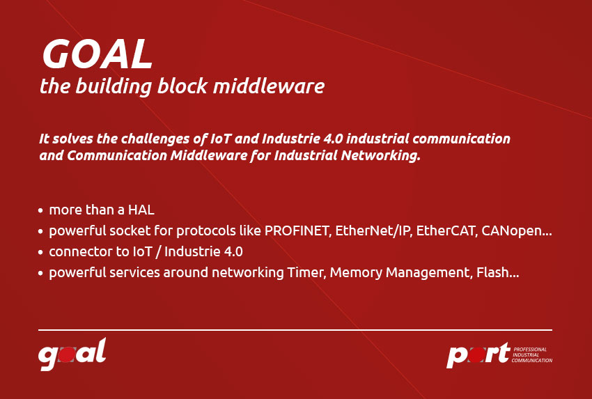
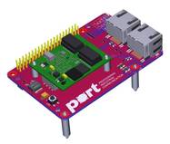
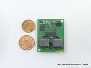
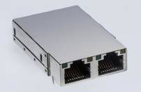
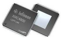
07/2022 Raspberry PI PROFINET and EtherNetIP - without additional hardware
Raspberry PI PROFINET and EtherNetIP - without additional hardware port's technology platform (middleware) GOAL is now also available for the Raspberry PI.With the GOAL solution, the Raspberry PI is "ready for" PROFINET and EtherNetIP......
06/2022 OPC UA - port industrial automation GmbH becomes a member of the OPC Foundation
port's middlerware GOAL is now being expanded with the integration of an OPC UA stack. The GOAL OPC UA protocol stack provides an API to implement an OPC UA server. There exist two versions. port GmbH offering the "Nano Embedded......